中文版
中文版 English
专业的电能质量的处理及稳定电压的设备
治理电力污染,稳定电压系统工程服务厂家
- 质量保障
- 高效安全
- 全自动
- 免维护
13560785740


功能:调压器系列产品是针对农网等供电半径长,负荷变化大而造成的供电末端电压低的现场而开发的产品,该产品对后端电压起到调节﹑稳压的作用,可有效解决配电网末端低电压的问题。
二、工作原理
该系列产品主要由交流旁路单元、功率变压器、整流单元、逆变单元、输入输出配电及保护、通讯单元等组成。
当市电输入电压在允许波动范围内,系统工作在交流旁路模式;当负荷加重导致“低电压”现象或者负荷降低导致“高电压”现象时,系统从旁路模式切换到整流逆变模式。整流单元由数字信号处理器控制IGBT模块输出稳定的内部直流电压,同时整流单元具有稳压功能,能够抑制输入市电电压的波动,逆变单元根据当前市电电压大小,计算出需要补偿电压,逆变单元输出相应电压通过变压器叠加到市电上,一起供给负载,从而解决了“低电压”或“高电压”问题。

图1 调压器 原理图
三、技术规格
| DNAM-单相末端电压补偿装置 | ||||
| 电气规格 | 输入电压 | 120V -270V | ||
| 相数 | 单相 | |||
| 额定输出电压 | 220Vrms/230Vrms 面板可设 | |||
| 频率 | 50Hz±10% | |||
| 额定输出容量 | 10kVA | 20kVA | 30kVA | |
| 逆变过载能力 | <1.05倍额定功率可长期过载,1.05倍至1.1倍功率可过载1小时后转旁路,1.1倍至1.25倍功率过载10分钟转旁路,1.25倍至1.5倍功率过载1分钟转旁路,1.5倍功率以上过载0.2秒转旁路 | |||
| [敏感词]效率 | >96.5% | |||
| 通信接口 | 干接点 | 1个EPO | ||
| 通信 | RS485,WIFI(选配) | |||
| 环境规格 | 使用场所 | 室外 | ||
| 工作海拔 | 低于1000米,高于1000米时降额使用 | |||
| 存储温度 | -20℃ ~ +70℃ | |||
| 工作温度 | -10℃ ~ +40℃ | |||
| 湿度 | 小于95%RH,无水珠凝结 | |||
| 振动 | 小于5.9米/秒²(0.6g) | |||
| 结构 | 防护等级 | IP43 | ||
| 尺寸 | 600*600*920 | |||
| 一体式产品净重 | 75kg/90kg/100kg | |||
| 冷却方式 | 智能风冷 | |||
| 规格 | DNAM三相末端电压补偿装置 |
| 额定输入电压 | 380V |
| 额定输入电流 | 152A |
| 额定输出电压 | 390V |
| 额定输出电流 | 148A |
| 交流输出类型 | (3W+N+PE)三相四线 |
| 额定容量 | 100kVA |
| 输入电压范围 | AC 380V(+32% ,-40%) |
| 额定电网频率 | 50Hz±5% |
| 稳压精度 | 1% |
| 响应时间 | <5ms |
| 电压总畸变率 | <4% |
| 工作环境温度 | -25℃~+55℃(>45℃降额) |
| 工作环境湿度 | <95%RH ,无凝露 |
| 冷却方式 | 智能风冷 |
| 防护等级 | IP44 |
| 工作海拔 | <4000 米(大于 2000 米需降额使用) |
| 噪音 | <65dB |
| 保护功能 | 过载保护、过温保护、过压保护、欠压保护、过流保护、过频保护、欠频保护等 |
| 界面显示 | 设备、电网,负载、温度数据显示、参数设定、运行状态显示、开关机控制等 |
| 通讯方式 | Modbus-RS485 、WIFI |
| 尺寸 | 451mm(宽) × 1020mm(高) × 800mm(深) |
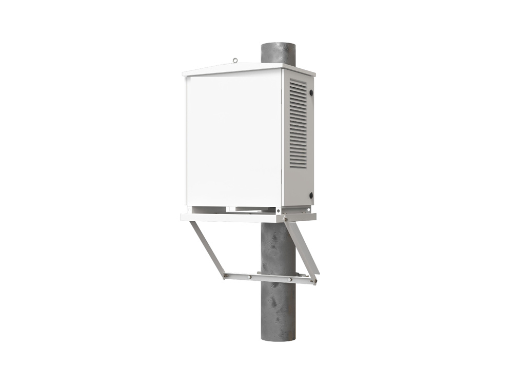
四、安装方式
安装方式包括户外杆三角支架安装,如图3-1。

图3-1 调压器安装方式示意图
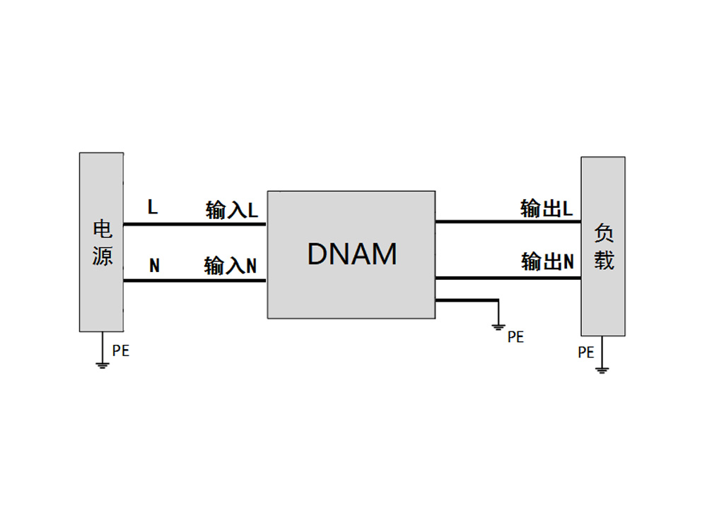
3.2 电气安装
3.2.1 单机配电
单机配电时,火线、N线、PE线连接方式如图3-2所示。

图3-2 单机配电接线示意图
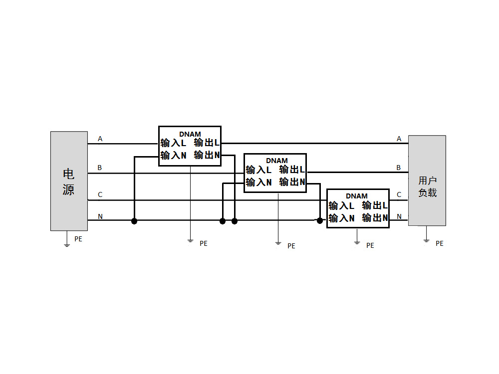
3.2.2 组三相配电
组三相时三相独立工作,接线示意图如下。

图3-3 组三相时示意图
Function:The voltage regulator series products are developed for sites with long power supply radius and large load changes, such as rural power grids, resulting in low voltage at the end of the power supply. This product plays a role in regulating and stabilizing the back-end voltage, effectively solving the problem of low voltage at the end of the distribution network.
2、 Working principle
This series of products mainly consists of AC bypass units, power transformers, rectifier units, inverter units, input-output distribution and protection, communication units, etc.
When the input voltage of the mains is within the allowable fluctuation range, the system operates in AC bypass mode; When the increase in load leads to the phenomenon of "low voltage" or the decrease in load leads to the phenomenon of "high voltage", the system switches from bypass mode to rectifier inverter mode. The rectifier unit is controlled by a digital signal processor to output a stable internal DC voltage from the IGBT module. At the same time, the rectifier unit has a voltage stabilization function, which can suppress fluctuations in the input mains voltage. The inverter unit calculates the required compensation voltage based on the current mains voltage, and the corresponding voltage output by the inverter unit is superimposed on the mains voltage through a transformer to supply the load together, thus solving the problem of "low voltage" or "high voltage".
Figure 1 Schematic diagram of voltage regulator
3、 Technical specifications
| DNAM single-phase terminal voltage compensation device | ||||
| Electrical specifications | input voltage | 120V -270V | ||
| phase number | single-phase | |||
| rated output voltage | 220Vrms/230Vrms panels can be set | |||
| frequency | 50Hz±10% | |||
| rated output capacity | 10kVA | 20kVA | 30kVA | |
| Inverter overload capacity | <1.05 times the rated power can be overloaded for a long time, 1.05 to 1.1 times the power can be overloaded for 1 hour before switching to the bypass, 1.1 to 1.25 times the power can be overloaded for 10 minutes before switching to the bypass, 1.25 to 1.5 times the power can be overloaded for 1 minute before switching to the bypass, and over 1.5 times the power can be overloaded for 0.2 seconds before switching to the bypass | |||
| Maximum efficiency | >96.5% | |||
| communication interface | dry contact | 1 EPO | ||
| communication | RS485, WIFI (optional) | |||
| Environmental Specifications | Usage location | outdoors | ||
| Working altitude | Below 1000 meters, use with reduced rating when above 1000 meters | |||
| Storage temperature | -20℃ ~ 70℃ | |||
| Operating Temperature | -10℃ ~ 40℃ | |||
| humidity | Less than 95% RH, no condensation of water droplets | |||
| vibration | Less than 5.9 meters per second ² (0.6g) | |||
| structure | Protection level | IP43 | ||
| size | 600*600*920 | |||
| Net weight of integrated product | 75kg/90kg/100kg | |||
| cooling method | Smart Air Cooling | |||
| Specifications | DNAM three-phase terminal voltage compensation device |
| Rated input voltage | 380V |
| input current | 152A |
| rated output voltage | 390V |
| output current | 148A |
| Communication output type | (3W N PE) three-phase four wire |
| Rated capacity | 100kVA |
| Input Voltage | AC 380V( 32% ,-40%) |
| Rated grid frequency | 50Hz±5% |
| voltage regulation accuracy | 1% |
| response time | <5ms |
| Total voltage distortion rate | <4% |
| Ambient Temperature | -25 ℃~55 ℃ (derating at>45 ℃) |
| Working environment humidity | <95%RH , No condensation |
| cooling method | Smart Air Cooling |
| Protection level | IP44 |
| Working altitude | <4000 meters (use with reduced rating if greater than 2000 meters) |
| noise | <65dB |
| protection function | Overload protection, over temperature protection, over voltage protection, under voltage protection, over-current protection, over frequency protection, under frequency protection, etc |
| interface display | Equipment, power grid, load, temperature data display, parameter setting, operating status display, power on/off control, etc |
| contact method | Modbus-RS485 、WIFI |
| size | 451mm (width) x 1020mm (height) x 800mm (depth) |
4、 Installation method
The installation method includes the installation of outdoor pole triangular brackets, as shown in Figure 3-1.
Figure 3-1 Schematic diagram of installation method for voltage regulator
3.2 Electrical Installation
3.2.1 Single machine power distribution
When distributing power individually, the connection methods of live wire, N-wire, and PE wire are shown in Figure 3-2.
Figure 3-2 Schematic diagram of single machine power distribution wiring
3.2.2 Three phase power distribution group
When assembling three phases, they work independently. The wiring diagram is shown below.
Figure 3-3 Schematic diagram of three-phase group