高低压无源无功补偿成套装置 一、应用场合 1、大功率半导体整流装置,包括直流电机、变频调速电机较多的场合 电解铝、中频炉、轧机等,半导体器件在关断与开通的过程中会产生与其接线方式有关的特征谐波,其流入系统的谐波电流会影响变压器和电动机等的正常工作,造成其过载甚至烧毁。
2、电力机车、单相用电负荷或者三相严重不平衡负载 目前各国正在运行时用的电气化铁路机车大多采用交流25~35KV电源,有前应变电站两相供电。这就不可避免的引起三相负荷不对称,由此向电力系统中一并注入谐波电流和付序电流。一般在牵引变压器的两个供电臂上装设容量相同的滤波器。
3、含铁磁特性器件的负载 在有些供用电系统中,变压器,铁心电抗器,当其工作在饱和状态时,由于磁化曲线的非线性,会产生一定次数的谐波,其中以三次为主,当系统存在并联补偿电容器时,电容器的容抗和系统感抗的一个合适比例,就会造成三次谐波的严重放大。
二、装置特点 高压成套装置按安装方式可分为两种形式:
-
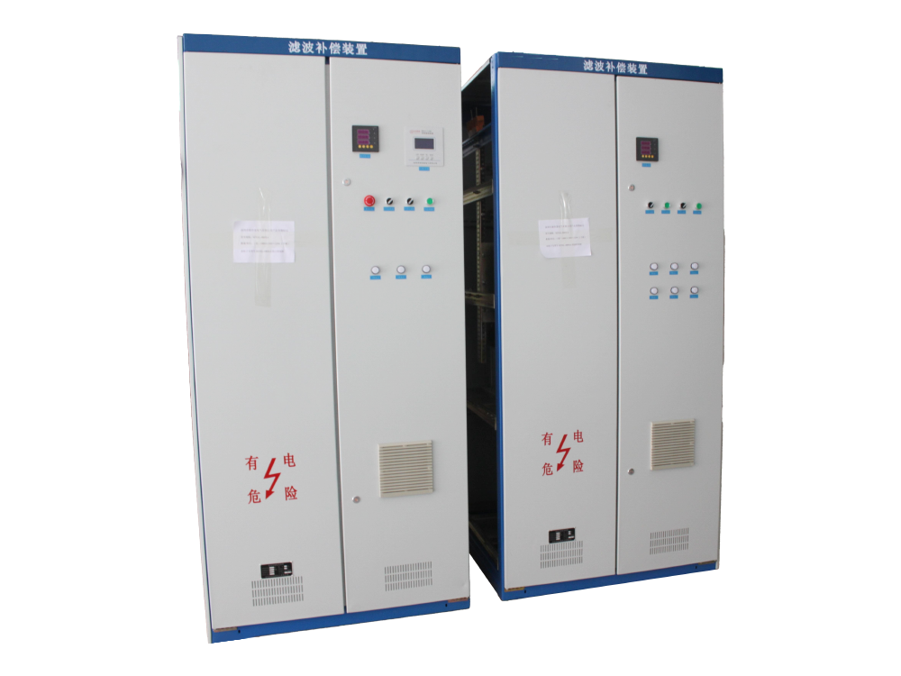
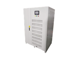
柜体式
整套装置全部安装于高压柜内,但如果采用空心滤波电抗器,电抗器不宜安装在柜体内,如果受场地影响,必须在柜体内安装,则必须采取磁屏蔽措施。
其特点是:装置小型化,为运输方便和减小占地面积,成套装置结构紧凑,布局合理,充分考虑了安装和运行维护的简单和直观。
-
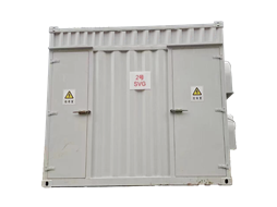
框架式
滤波成套装置常用的安装形式,整套装置包含:
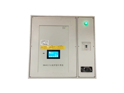
a)进线及保护柜:内含断路器、隔离开关和电流互感器等;
b)继电保护屏:实现保护、自动投切、测量及通讯等功能;
c)一次元件:包括滤波电容器、滤波电抗器、放电线圈、避雷器和喷逐式熔断器等;
d)钢构架及围栏等。
系列性能好:成套装置的主设备、钢构架和零配件通用化适当划分不同容量等级。对断路器等控制设备、保护装置和自动投切的选择,以及单台电容器的保护方式等充分尊重用户的意见和建议,厂家按合同要求成套供货。
灵活性强:可以满足城市电网、农村电网和重工业负荷对电能质量的不同要求,可以同时补偿无功,提高系统电压,改善电压畸变率。
适应性强:我国幅员辽阔,南北方、寒热带和高海拔等区域气候条件差异大,成套装置的不同设计充分满足了其在不同气候条件下的可靠运行。
成套装置按投切方式可分为以下几种: 1)手动投切 整套装置可由几组或一组滤波器构成,由操作人员手动操作。
手动投切的滤波装置一般适合于有人值班的变电站或工厂配电系统。 2)自动投切 整套装置可由几组或一组滤波器构成,由控制器控制按顺序自动投切,控制参数可选谐波发生量或者电压无功等。
自动投切的滤波装置一般适合于无人值班的变电站或工厂配电系统或者是系统谐波(无功)变化比较频繁的场合。 三、订货须知 滤波装置设计的基本原则是,在确定的系统和谐波源下,以少的投资达到母线电压畸变率和谐波电流值符合规定的指标,并满足无功补偿要求,保证装置安全可靠和经济运行。为此,在滤波装置设计之前,用户要求提供以下信息:
系统主接线及设备(主变压器、电缆等)参数
电网运行参数(电压、频率变化、电压不平衡等)
系统的谐波阻抗特性
负荷特性(负荷的性质、大小、谐波阻抗等)
谐波源的特性(谐波次数、幅值和波动性)
系统的背景谐波水平
无功补偿要求和要求达到的谐波指标
如果原有并联补偿电容器,应提供其安装位置、容量、电压、接线方式及电抗率等
heightPassive compressionReactive power compensationComplete set of equipment 1、 Application scenarios 1high-powersemiconductorRectification deviceIncluding situations where there are many DC motors and variable frequency speed regulating motors Electrolytic aluminum, intermediate frequency furnace, rolling millDuring the process of turning off and on semiconductor devices, characteristic harmonics related to their wiring methods are generated. The harmonic currents flowing into the system can affect the normal operation of transformers and motors, causing them to overload or even burn out.
2Electric locomotiveSingle phase electrical load or three-phase severely unbalanced load At present, most of the electrified railway locomotives in operation in various countries use AC 25-35KV power supply, with two-phase power supply from the front strain power station. This inevitably causes three-phase load asymmetry, thereby injecting harmonic currents and sequence currents into the power system together. Generally, filters with the same capacity are installed on the two power supply arms of the traction transformer.
3Negative of devices with ferromagnetic propertiesload In some power supply and consumption systems,Transformer, iron core reactorWhen it operates in a saturated state, due to the nonlinearity of the magnetization curve, a certain number of harmonics will be generated, with the third harmonic being the main one. When there are parallel compensation capacitors in the system, a suitable ratio between the capacitance reactance of the capacitors and the system inductance reactance will cause severe amplification of the third harmonic.
IIDevice features High voltage complete sets of equipment can be divided into two forms according to installation methods:
-
Cabinet type
The entire device is installed inside the high-voltage cabinet, but if hollow filter reactors are used, they should not be installed inside the cabinet. If they are affected by the site and must be installed inside the cabinet, magnetic shielding measures must be taken.
Its characteristics are: miniaturization of the device, convenient transportation and reduced footprint, compact structure of the complete set of devices, reasonable layout, fully considering the simplicity and intuitiveness of installation and operation maintenance.
-
Framework style
The commonly used installation form for filtering equipment includes:
a) Incoming and protective cabinets: containing circuit breakers, isolating switches, and current transformers, etc;
b) Relay protection screen: realizing functions such as protection, automatic switching, measurement, and communication;
c) Primary components: including filtering capacitors, filtering reactors, discharge coils, lightning arresters, and spray type fuses, etc;
d) Steel frame and fence, etc.
Good series performance: The main equipment, steel structure, and spare parts of the complete set of equipment are standardized and appropriately divided into different capacity levels. The selection of control equipment such as circuit breakers, protective devices, and automatic switching, as well as the protection methods for individual capacitors, fully respects the opinions and suggestions of users, and the manufacturer supplies complete sets according to the contract requirements.
Strong flexibility: It can meet the different requirements of urban power grids, rural power grids, and heavy industrial loads for power quality, and can simultaneously compensate for reactive power, increase system voltage, and improve voltage distortion rate.
Strong adaptability: China has a vast territory with significant differences in climate conditions between the north and south, cold and tropical regions, and high-altitude areas. The different designs of the complete equipment fully meet its reliable operation under different climate conditions.
Complete equipment according toThe cutting methods can be divided into the following types: 1) Manual switching The entire device can be composed of several sets or one set of filters, which can be manually operated by the operator.
Manual switching filtering devices are generally suitable for substations or factory distribution systems with personnel on duty. 2) Automatic switching The entire device can be composed of several sets or one set of filters, which are automatically switched in sequence by the controller. The control parameters can be selected from harmonic generation or voltage reactive power.
Automatic switching filtering devices are generally suitable for unmanned substations or factory distribution systems, or for situations where system harmonics (reactive power) change frequently. IIIOrdering Notice The basic principle of designing a filtering device is to achieve the specified indicators of bus voltage distortion rate and harmonic current value with minimal investment under a determined system and harmonic source, and to meet the requirements of reactive power compensation, ensuring the safe, reliable, and economical operation of the device. Therefore, before designing the filtering device, users are required to provide the following information:
System main wiring and equipment (main transformer, cable, etc.) parameters
Operating parameters of the power grid (voltage, frequency variation, voltage imbalance, etc.)
Harmonic impedance characteristics of the system
Load characteristics (nature, size, harmonic impedance, etc. of the load)
Characteristics of harmonic sources (harmonic order, amplitude, and fluctuation)
The background harmonic level of the system
Reactive power compensation requirements and required harmonic indicators
If there is an existing parallel compensation capacitor, its installation location, capacity, voltage, wiring method, and reactance rate should be provided
 中文版
中文版 English